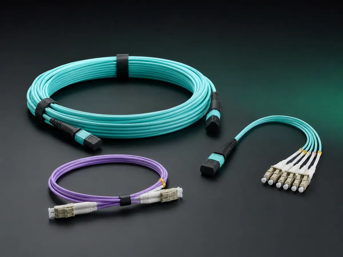
MPO/MTP Fibre Assemblies Buyer’s Guide should turn buyer selection into a configuration that can be built, inspected and repeated. The practical objective is to select an assembly that matches the real channel; the output is a controlled purchase specification, not a catalogue description or a broad compatibility promise.
MPO is the generic multi-fibre interface, while MTP is a branded high-performance implementation. Neither name alone defines fibre count, connector gender, pinning, key orientation, polarity, fibre grade or loss class. For network buyers and designers, those fields must be explicit before price, sample approval or installation can be judged.
Translate the project into an assembly specification: MPO versus MTP interface
Make MPO versus MTP interface visible on the controlled part number, drawing or route schedule, and connect it to 8/12/16/24 fibres. Where two suppliers use different terminology, resolve the difference with pin diagrams, lane maps and measurable limits instead of accepting a verbal equivalence.
Check male or female connector under conditions that represent installation and service, not only at a clean bench. Preserve both passing and failing observations. That evidence helps network buyers and designers distinguish contamination, polarity, geometry, mechanical stress and transceiver-margin problems without random component swapping.
Choose the MPO or MTP interface architecture: Male or female connector
Start this stage with male or female connector, then confirm key orientation against the actual endpoints and route. In an MPO/MTP channel, a component can mate physically and still send lanes to the wrong positions or consume more optical margin than the design allows. Record unknowns openly and assign each one to engineering, purchasing or the installer before release.
The main error to prevent is ordering by connector name while ignoring pinning, polarity and fibre count. Use Method A/B/C polarity as an acceptance field with a drawing, measured value or named test method. A supplier statement is useful context, but the approval record must show which exact part, sample, lot and configuration the evidence covers.
Map every optical lane before ordering: Method A/B/C polarity
Review Method A/B/C polarity together with OS2/OM4 fibre; neither should be selected in isolation. Follow the path from the transmit lanes, through trunks, cassettes or harnesses, to the receive lanes and note every mating pair. This makes hidden assumptions visible before a cable reaches the rack or field cabinet.
For buyer selection, require evidence for standard or low-loss grade that another reviewer can reproduce. Keep raw per-lane results, equipment identity, calibration status, date and sample identity. Summaries such as “tested” or “compatible” do not replace a fibre map, loss file or controlled construction record.
Specify connector gender, pins and key orientation: Standard or low-loss grade
Treat standard or low-loss grade as a system choice and verify its interaction with jacket and length. Base-8, base-12 and base-16 designs can coexist in a facility, but an undocumented transition may strand fibres, reverse lanes or require an unplanned cassette. The bill of materials and port map should show the transition deliberately.
A defensible a controlled purchase specification also states the boundary for MPO versus MTP interface. Approval applies only to the documented assembly, route and optical architecture. If a ferrule, fibre, breakout, polishing process or endpoint changes, compare the revision with the original risk assessment and repeat the affected tests.
Build an end-to-end polarity map: MPO versus MTP interface
Make MPO versus MTP interface visible on the controlled part number, drawing or route schedule, and connect it to 8/12/16/24 fibres. Where two suppliers use different terminology, resolve the difference with pin diagrams, lane maps and measurable limits instead of accepting a verbal equivalence.
Check male or female connector under conditions that represent installation and service, not only at a clean bench. Preserve both passing and failing observations. That evidence helps network buyers and designers distinguish contamination, polarity, geometry, mechanical stress and transceiver-margin problems without random component swapping.
Select fibre grade and cable construction: Male or female connector
Start this stage with male or female connector, then confirm key orientation against the actual endpoints and route. In an MPO/MTP channel, a component can mate physically and still send lanes to the wrong positions or consume more optical margin than the design allows. Record unknowns openly and assign each one to engineering, purchasing or the installer before release.
The main error to prevent is ordering by connector name while ignoring pinning, polarity and fibre count. Use Method A/B/C polarity as an acceptance field with a drawing, measured value or named test method. A supplier statement is useful context, but the approval record must show which exact part, sample, lot and configuration the evidence covers.
Set measurable optical acceptance limits: Method A/B/C polarity
Review Method A/B/C polarity together with OS2/OM4 fibre; neither should be selected in isolation. Follow the path from the transmit lanes, through trunks, cassettes or harnesses, to the receive lanes and note every mating pair. This makes hidden assumptions visible before a cable reaches the rack or field cabinet.
For buyer selection, require evidence for standard or low-loss grade that another reviewer can reproduce. Keep raw per-lane results, equipment identity, calibration status, date and sample identity. Summaries such as “tested” or “compatible” do not replace a fibre map, loss file or controlled construction record.
Inspect end faces and connector geometry: Standard or low-loss grade
Treat standard or low-loss grade as a system choice and verify its interaction with jacket and length. Base-8, base-12 and base-16 designs can coexist in a facility, but an undocumented transition may strand fibres, reverse lanes or require an unplanned cassette. The bill of materials and port map should show the transition deliberately.
A defensible a controlled purchase specification also states the boundary for MPO versus MTP interface. Approval applies only to the documented assembly, route and optical architecture. If a ferrule, fibre, breakout, polishing process or endpoint changes, compare the revision with the original risk assessment and repeat the affected tests.
Test the named configuration, not a generic family: MPO versus MTP interface
Make MPO versus MTP interface visible on the controlled part number, drawing or route schedule, and connect it to 8/12/16/24 fibres. Where two suppliers use different terminology, resolve the difference with pin diagrams, lane maps and measurable limits instead of accepting a verbal equivalence.
Check male or female connector under conditions that represent installation and service, not only at a clean bench. Preserve both passing and failing observations. That evidence helps network buyers and designers distinguish contamination, polarity, geometry, mechanical stress and transceiver-margin problems without random component swapping.
Release production with traceability: Male or female connector
Start this stage with male or female connector, then confirm key orientation against the actual endpoints and route. In an MPO/MTP channel, a component can mate physically and still send lanes to the wrong positions or consume more optical margin than the design allows. Record unknowns openly and assign each one to engineering, purchasing or the installer before release.
The main error to prevent is ordering by connector name while ignoring pinning, polarity and fibre count. Use Method A/B/C polarity as an acceptance field with a drawing, measured value or named test method. A supplier statement is useful context, but the approval record must show which exact part, sample, lot and configuration the evidence covers.
Preserve identity through moves, adds and changes: Method A/B/C polarity
Review Method A/B/C polarity together with OS2/OM4 fibre; neither should be selected in isolation. Follow the path from the transmit lanes, through trunks, cassettes or harnesses, to the receive lanes and note every mating pair. This makes hidden assumptions visible before a cable reaches the rack or field cabinet.
For buyer selection, require evidence for standard or low-loss grade that another reviewer can reproduce. Keep raw per-lane results, equipment identity, calibration status, date and sample identity. Summaries such as “tested” or “compatible” do not replace a fibre map, loss file or controlled construction record.
Approve exceptions and future revisions: Standard or low-loss grade
Treat standard or low-loss grade as a system choice and verify its interaction with jacket and length. Base-8, base-12 and base-16 designs can coexist in a facility, but an undocumented transition may strand fibres, reverse lanes or require an unplanned cassette. The bill of materials and port map should show the transition deliberately.
A defensible a controlled purchase specification also states the boundary for MPO versus MTP interface. Approval applies only to the documented assembly, route and optical architecture. If a ferrule, fibre, breakout, polishing process or endpoint changes, compare the revision with the original risk assessment and repeat the affected tests.
Release checklist for buyer selection
Release the order or installed channel only when the exact part identity, fibre and lane map, connector gender and pins, key orientation, polarity, fibre grade, cable construction, length, per-lane loss limits, labels and evidence package agree. The decision owner should sign the configuration and list any accepted deviation.
The completed record should allow a new reviewer to reproduce the decision without private messages or memory. Keep a controlled purchase specification with sample and lot identifiers, raw test files, drawings, approvals and revalidation triggers. This is the control that turns a successful sample into a dependable repeat order.
TECHNICAL RFQ
Turn your part number or project list into a reviewed quotation.
Share the available technical data. MingApex will structure the requirement, identify open compatibility questions and coordinate the supply review in China.
- Host platform or reference part number
- Speed, form factor and required reach
- Wavelength, fibre and connector
- Quantity, sample and delivery target
- OEM label or packaging requirement
- Destination country and Incoterm